When viewing results from an air dispersion model run, the primary concern of many modelers are conditions measured at receptors located in areas generally accessible by the public. This may preclude modeling from occurring within well-defined property boundaries that restrict public access to a facility.
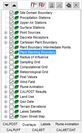
Lakes Environmental’s AERMOD View and CALPUFF View contain the Plant Boundary tool for defining a set of discrete receptors as the property boundary. Using this tool automatically adds a new layer to the project’s Overlays – the Plant Blanking Boundary layer.

Plant Boundary Tool
This layer fills in the bounds of the Plant Boundary with an opaque polygon that effectively hides all layers listed beneath it.
As shown in previous Modeling Tips, it is easy to remove onsite receptors that fall within the property boundary. Removing these receptors but leaving concentration contours can give the impression of calculated model results where they do not exist.
The images below display the impact of the Plant Blanking Boundary. The first image is the default image of a Plant Boundary featuring the Blanking layer enabled. The second image shows contours when the Blanking layer is disabled.
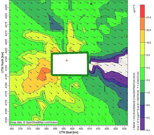
Blanking Layer Enabled
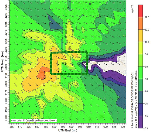
Blanking Layer Disabled
The Blanking layer is available for display via the Plant Blanking Boundary layer displayed in the Overlays Tree View.